MountainScope
by
PCAvionics
Display "Heads up" 3-D topography and
Aviation Data while Flying
Instructions and Review by Jack
Yeazel and Dale
DePriest
(25 Jan. 2003 Add Pocket PC Features)
PROGRAM OPERATION WITH A PC
PC INSTALLATION:
Windows-XP:
MountainScope was coded specifically for
Windows-XP, and the installation of about 500MB is quite simple. Should
the CD autorun not function, run CDautorun.exe from the disk.
Windows-98:
Here you will need to install Microsoft
Internet Explorer 5.5 or higher. In addition, to insure that the
Windshield View will work, you will need to get DirectX 9.0 (from the 'redist'
subdirectory on the CDROM). Also, you may need to get the latest
video drivers (available from your system or video card manufacturer),
but this wasn't necessary on the two review PCs.
OVERVIEW:
This program is designed to give the flyer
an additional measure of safety by displaying a situation awareness of
the surrounding terrain in plan and 3-D views with pictorial warnings when
approaching dangerous obstacles or terrain. It should be noted that
17% of General Aviation fatalities are caused by Controlled
Flight into Terrain.
This program uses the resources of the
US Geological Survey's Digital Elevation Model (DEM), water overlays, and
FAA flight information databases. DEM elevation points at 90-meter
intervals provide the basis of the topo and 3-D map displays to the viewer.
The program also displays aeronautical moving maps to provide guidance
to the closest airports and navaids in case of emergency or disorientation.
Flight Planning and Track Logging are additional features.
PROGRAM OPERATION:
In order to get started, there is usually
nothing to do except to click on the "GPS" button. Select "NMEA"
if using a non-Garmin unit or select "Garmin" (mode) for Garmin units.
NMEA updates at 2-second intervals while the Garmin mode updates each second.
The initial screen should immediately show your location on a topographic
map including pertinent aircraft information. Under the MENU key
is an option to use the program in a simulator mode.
MountainScope Screen
Initial 800x600 Screen:
The MountainScope topographic screen always
shows the two Nearest Airports and their elevations (here, PDK and MGE),
the two nearest Navaids, and the Lat/Long coordinates. 'PDK' is a
VOR on 166.60 MHz, and 'IPDK' is the Instrument landing localizer
on 111.10 MHz (all at the PDK airport, blue circle with runways) approximately
4nm in a direction of about 204°. A flashing "!"
is provided if any information is incorrect or missing.
In the above screen, the aircraft is 590
feet AGL (above ground level), approaching the IPDK localizer (the white
"feather") at 110 knots on a ground track of 174° magnetic, which is
also indicated by the compass circle. Color-coded arrows show the
relative bearings to the above information, and are also shown on the topo
map or edge of the compass circle, if off the map. At the bottom
of the screen are the present time, elapsed time, and radius of the zoomed
window in nautical miles.
Beneath those, a CDI (Course Deviation
Indicator) is displayed that shows the plane still about 3.5 "dots" to
the right of the runway centerline. This CDI is set up by clicking
on the sharpest point of a localizer arrow, where one gets a menu to set
up the indicator. A full deflection represents 2.5° off
the approach course to the selected LOC. The CDI also shows the ILS
identifier and the exact magnetic course to the airport.
The blue lines are the limits of classified
airspaces of commercial airports nearby, which are defined (in feet times
100) when clicking on them. These airspaces usually require two-way
communications and altitude reporting transponders. Light blue transparent
lines are enroute airways, and the white triangles are enroute intersections
and approach fixes, which can be identified by clicking on them.
Clicking on the screen provides a menu
(plus obstructions described below) to create a user waypoint (a cross)
at that point. The waypoint is then edited for a proper name and
comment. In the future, clicking on the waypoint reveals this data.
By clicking the ALL button under Nearest Navaids, one can select VOR, NDB,
or LOC to further refine the desired information.
Obstructions:
Clicking on the map allows one to zoom
in or out. Any obstruction near or above present altitude will show
in RED. A list and the altitudes of
the closest obstructing towers or buildings are provided where one clicks
on the map . Also at the bottom of the list is the elevation, bearing,
and distance to the terrain where you clicked.
Windshield View
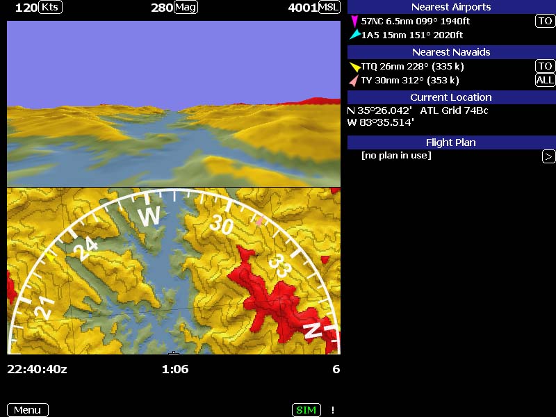
Windshield View:
Is activated by clicking on the map and
selecting Windshield View. Here the compass circle is only the forward
half with the aircraft at the bottom. The 3-D view at the top shows
the aircraft safely navigating between mountain ranges (yellow is within
2000' of present altitude and red is higher than the aircraft) over a river
valley and lake. The 'grid' is true N/S/E/W and aids in course awareness.
The aircraft is flying 120 knots (or MPH can be selected) at 4,001 feet
MSL. This box can show MSL, AGL, or the GND elevation. The
course over ground is 280° magnetic, but can be selected as true, if
desired. NOTE: GPS inputs show
COG (Course Over Ground) and not the aircraft heading.
Red areas are elevations above present
altitude. The yellow areas represents terrain within 2,000 feet of
present altitude, thus providing a margin of error between GPS altitude
and pressure altitude which could be up to 1,000'. Otherwise, terrain
is color-coded light green up to 1,000', dark green to 2,500', light beige
to 3,500', medium beige to 5,500', dark beige to 7,500', and brown from
that point up. Contour lines are shown at 500-foot intervals.
SIM Keys:
When these keys are activated, one can
increase the speed with the up arrow and decrease speed with the down arrow.
The right and left arrow changes heading, and an 'ascent' can be set up
by pressing "Z" or a descent with "A" provided there is some speed displayed.
If zero speed is displayed, the A and Z keys simply decrease or increase
altitude.
PROGRAM OPERATION WITH A POCKET PC:
POCKET PC INSTALLATION:
Installing the product on a Pocket PC
is almost identical to the installation of the windows version and for
that matter the operation of the product is identical as well except there
is no windshield view in this version and the keys are mapped differently.
The screen size is 320x240 which can be emulated using the PC version if
desired. The basic product needs about 5 Meg of memory for storage and
should be installed in ram. The maps themselves are variable sized, of
course, and will be automatically installed in ram but may be moved to
an expansion card to conserve ram space. They can be placed in a \Terrain
directory at the root of any card. This is likely to cause some reduction
in performance. Terrain maps are optional since the program will run without
them using a very low resolution backup database but they sure add a lot
of useful information. Maps can also be downloaded automatically as needed.
To use this feature simply create a flight plan in the PC product and then
push the flight plan to the Pocket PC. You will be offered a choice to
download the appropriate terrain maps as well.
The program arrived on a CDROM inside a
REAL hardcopy manual. If you really prefer a soft copy there is a PDF on
the CDROM and you can copy it to your Pocket PC to be used with acrobat
reader. The manual is well written and covers most of the operations you
might want to do. This is a welcomed addition to the product. Note that
you will need to read the manual as there is no online help in the software.
MountainScope was tested on an iPAQ 3970
with various gps devices including Garmin serial gps units, Compact Flash
units, and a Navman sleeve. The Compact Flash units were plugged into the
iPAQ via a memplug CF adapter.
OPERATION:
Once installed you can launch it from
the Pocket PC start menu. Prior to starting it you will want to ensure
that all other programs have been shutdown as they take up resources and
can slow the product down. As you can see from the picture at the right
there is no banner or any way to get back to any other program anyway without
exiting this one. All of the keys have been captured by the program as
well. I had to fake the picture from the PC as my screen capture
utility wouldn't work. But the picture looks exactly the same except on
my Pocket PC the SIM mode was really in gps mode and the speed wasn't 0!
The picture shows a plane taking off from
an small airport near my home and flying over the top of my house. Other
things you can notice is that there is another small airport 6.3 nautical
miles from my house in the direction shown. A color Pocket PC is pretty
essential to the operation of this product as color is used extensively.
For example the small arrowheads (called bugs in the manual) are color
coded to match the information at the bottom of the display with the object
on the screen (or to point in the direction of the object relative to the
screen). In this case the screen is displaying the two nearest airports.
It can switched to display the two closest navaids, the current flight
plan, or the current location.
Most objects can be tapped to bring up
a menu whether they are on the screen or in the display below the screen.
The soft buttons can also be tapped to either bring up a menu or to toggle
a choice. There are digital displays of current speed (nm or statute miles),
direction on the ground (relative to true or magnetic north), and elevation
(above terrain, above sea level, or current ground level elevation). Current
clock time (only zulu), a resettable travel time, and the current zoom
level are shown below the elevation. The red areas show that there are
hills above my current altitude and I had better be climbing or turning
quickly.
The rocker keypad can be used to zoom the
picture (up or down). It can also toggle the nearest airport / nearest
navaid / current location / flight plan display (left or right). Depressing
the rocker pad will reset the elapsed timer.
NAVIGATION:
While the display can provide a great
deal of situation awareness the program provides even more features through
the use of flight plans and the CDI display.
The CDI (course deviation indicator) display
can be turned on by tapping the desired airport on the screen or the airport
line in the closest airport display or flight plan display. This will bring
up a menu with the choices for displaying the CDI display for the various
runways and directions. It is also possible to tap on tip of the LOC display
arrow on the screen to turn on the CDI indicator. Tapping the CDI display
itself will turn it off. This display is modeled after the LOC indicator
on suitably equipped aircraft but it works from internal database information
and the gps thus it will work even on airports without a LOC signal so
long as the runway direction is in the database.
The flight plan feature can be as simple
as just identifying the destination airport as shown here or can be a full
blown multi-turn flight with intermediate stops. The turns can be tappable
objects on the map or they can be user defined waypoints for any location
on the map. A flight plan is built by choosing the destination, the starting
point and then adding as many checkpoints as desired.
Generally a complicated flight plan is
built in simulation mode and can even be built on the PC, taking advantage
of the larger display size, and then downloaded to the Pocket PC. Flight
plans can be saved and reloaded later. They can also be modified as needed
during the flight by adding checkpoints. When a flight plan is in use the
ete (estimated time enroute) will be given and the program will automatically
switch to the next point as points are passed.
Objects in the database are selectable
by tapping the menu icon in the lower left corner and selecting lookup.
A list of the database objects will appear including the user defined waypoints.
Tap the kind of object you want and a small form will appear with the first
letters of all the objects in the database that matches the description.
Tapping this letter will bring up an choice form with the next letter.
Continue this until the desired object is found and information about that
object will be displayed. The item can be viewed on the map if you are
in simulation mode by tapping jump or it can be the destination in a new
flight plan or a checkpoint in the current flightplan by tapping the appropriate
button. If there is more information than can be displayed a full screen
mode can be selected or the data can be scrolled using a scroll bar or
the rocker up/down keys. Object information can also be reached graphically
by tapping on the object and then selecting its name from the menu. There
is no way to browse the database.
Other items on the main menu include display
choices, working with the tracklog, enabling simulation keys (overrides
normal key binding) and the quit command. You can record a tracklog of
your travels and then save it. It can be loaded but not run in this program.
It can be run in the Microsoft Flight Simulator 2003.
The SIM button can be tapped to reveal
the gps choices. The com port can be selected and the type of gps. The
baud rate is hard coded based on the gps type. It will normally take two
taps to complete this selection since you need to select both a gps and
a com port. Selecting None returns to simulation mode.
TIPS and LIMITATIONS:
The following observations are in no particular
order and are only numbered for reference.
-
Flight Plans take a snapshot of any user waypoints
used in the route. If the name or location of the user waypoint is changed
this will not be reflected in the route.
-
Checkpoints are added to the correct place
automatically however I found a few cases where they were not added correctly.
The flight plan file is in XML format and can be edited on a PC using any
text editor to correct this.
-
The data in the database gets out of date
quickly. You will need a subscription service and internet access to download
updated data every month. You can download data in advance if you wish.
The product will warn you when the data is about to expire but the product
is still usable with old data.
-
The gps status only indicates reception of
gps data. There is an attempt to recognize 2D fixes but the method used
does not work with all gps devices that I tested. You should ensure the
gps has a good sky view (an external antenna on the outside of the plane
is recommended) and you need to be conscious of the altitude numbers. If
they quit moving do not trust them. (There is a fix coming for this problem.)
The gps button will flash if gps lock is lost.
-
On Garmin receivers the proprietary altitude
sentence is used for altitude display and calculations. This means that
if you use a Garmin unit that has a barometer in it then this barometric
data will be used rather than the gps computed altitude.
-
Users of gps units utilizing the SiRF chipset
should know that most implementations of this chipset do not provide magnetic
variation correction or geoid altitude correction for Mean Sea Level. Mountainscope
detects the lack of magnetic headings an correctly computes this automatically
based on your location however it does not correct for the altitude errors.
User may find up to 170 feet of elevation error on these devices depending
on location.
-
If you are a pilot for whom IFR means I Follow
Roads, you will find that this product does not display roads on the map.
This is planned for a future release.
-
Display choices are not saved between sessions.
-
There is no actual route guidance except to
follow the line on the map.
-
The maps cannot be panned. The workaround
is to select an object where you want the map to be and then jump to this
location, zooming in and out as needed.
CONCLUSIONS:
This product offers some unique features
for the pilot and provides excellent topographic/aeronautical charts. We
found the product worked well and had no crashes during our testing. The
PCAvionics team is aware of this review and are working on some of the
limitations mentioned.
Return to GPS
Information home page