Modification to cause the GPS to automatically turn ON when external power is applied
CAUTION: While this modification is simple for
an experienced electronic technician, it is ALWAYS possible that
you will destroy your GPS in the process of doing this modification even
if you are careful. If this procedure is not FAMILIAR to you,
do not even attempt to do this modification. The author takes no
responsibility for any unfortunate outcome of this modification!
Here
is the rough information for the modification:
Parts
needed: a 1K, 1/4watt resistor, a diode 1N914 or equal
1.Open
the G III+ case by removing the 6 screws.
2.
After opening the case, locate the white power connector.
You
might find that unplugging it will help your work.
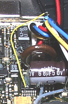
3.
Locate the pin 2 of 1435 chip. The 1435 is just under the 68uf cap in the
above photo.
4.
Locate the external power line. I'm not sure the pin number. If you refer
to the picture below, it's the rightmost pin of the white power connector. 5. Wire a line from 1435 chip pin 2 to the cathode of the
diode. Then wire the anode of diode to the 1K resistor. Then connect the other
side of 1K resistor to the external power input line as
shown. That is PIN
2-------+<------------^^^^------ ext. power
diode resistor 6.
The chip 1435 is a SMT IC. You have to be very careful.To
do this modification,
some SMT soldering skill is necessary. Modification designed by: Steven
Veg
With Image Enhancement and graphic formatting
with thanks to Larry Glickman.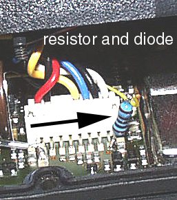
Dean Bennett reports that this procedure also works on the original III.